Laser welding focusing method
When a laser comes into contact with a new device or conducts a new experiment, the first step must be focusing. Only by finding the focal plane can other process parameters such as defocusing amount, power, speed, etc. be correctly determined, so as to have a clear understanding.
The principle of focusing is as follows:
Firstly, the energy of the laser beam is not evenly distributed. Due to the hourglass shape on the left and right sides of the focusing mirror, the energy is most concentrated and strongest at the waist position. To ensure processing efficiency and quality, it is generally necessary to locate the focal plane and adjust the defocusing distance based on this to process the product. If there is no focal plane, subsequent parameters will not be discussed, and debugging new equipment should also first determine whether the focal plane is accurate. Therefore, locating the focal plane is the first lesson in laser technology.
As shown in Figures 1 and 2, the focal depth characteristics of laser beams with different energies are different, and the galvanometers and single mode and multimode lasers are also different, mainly reflected in the spatial distribution of capabilities. Some are relatively compact, while others are relatively slender. Therefore, there are different focusing methods for different laser beams, which are generally divided into three steps.
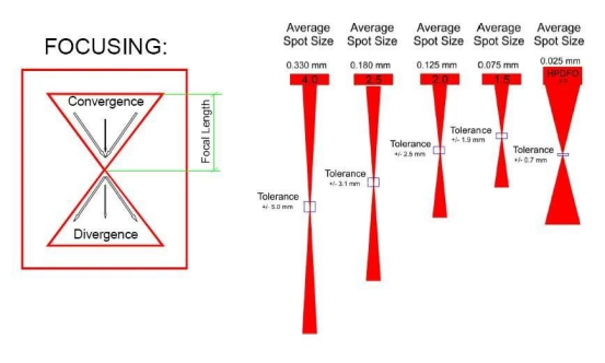
Figure 1 Schematic diagram of focal depth of different light spots
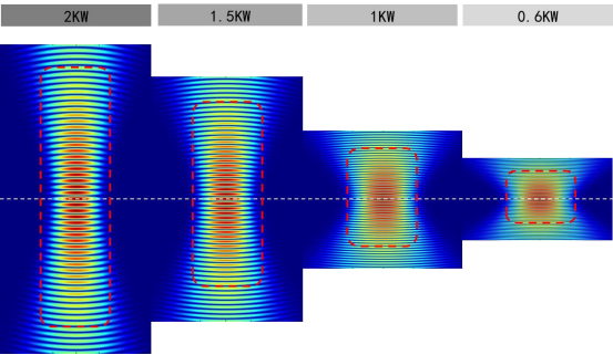
Figure 2 Schematic diagram of focal depth at different powers
Guide spot size at different distances
Slanting method:
1. Firstly, determine the approximate range of the focal plane by guiding the light spot, and determine the brightest and smallest point of the guiding light spot as the initial experimental focus;
2. Platform construction, as shown in Figure 4
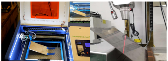
Figure 4 Schematic diagram of oblique line focusing equipment
2. Precautions for diagonal strokes
(1) Generally, steel plates are used, with semiconductors within 500W and optical fibers around 300W; The speed can be set to 80-200mm
(2) The larger the inclined angle of the steel plate, the better, try to be around 45-60 degrees, and set the midpoint at the coarse positioning focal point with the smallest and brightest guiding light spot;
(3) Then start stringing, what effect does stringing achieve? In theory, this line will be symmetrically distributed around the focal point, and the trajectory will undergo a process of increasing from large to small, or increasing from small to large and then decreasing;
(4) Semiconductors find the thinnest point, and the steel plate will also turn white at the focal point with obvious color characteristics, which can also serve as a basis for locating the focal point;
(5) Secondly, the fiber optic should try to control the back micro penetration as much as possible, with micro penetration at the focal point, indicating that the focal point is at the midpoint of the back micro penetration length. At this point, the coarse positioning of the focal point is completed, and the line laser assisted positioning is used for the next step.
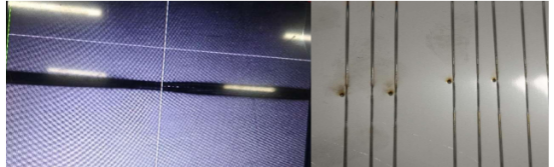
Figure 5 Example of diagonal lines
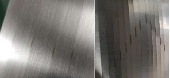
Figure 5 Example of diagonal lines at different working distances
3. The next step is to level the workpiece, adjust the line laser to coincide with the focus due to the light guide spot, which is the positioning focus, and then perform the final focal plane verification
(1) Verification is carried out through the use of pulse points. The principle is that sparks are splashed at the focal point, and the sound characteristics are obvious. There is a boundary point between the upper and lower limits of the focal point, where the sound is significantly different from the splashes and sparks. Record the upper and lower limits of the focal point, and the midpoint is the focal point,
(2) Adjust the line laser overlap again, and the focus is already positioned with an error of about 1mm. Can repeat experimental positioning to improve accuracy.
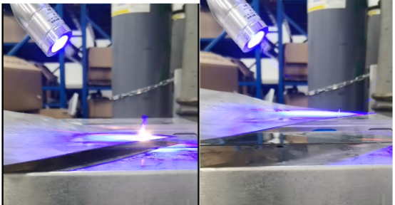
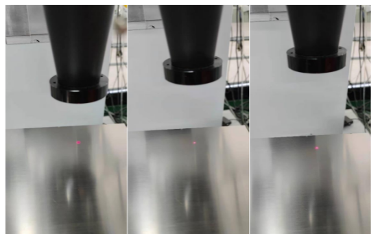
Figure 6 Spark Splash Demonstration at Different Working Distances (Defocusing Amount)
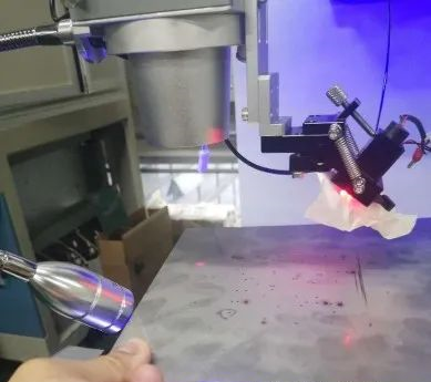
Figure 7 Schematic diagram of pulse dotting and focusing
There is also a dotting method: suitable for fiber lasers with larger focal depth and significant changes in spot size in the Z-axis direction. By tapping a row of dots to observe the trend of changes in the points on the surface of the steel plate, each time the Z-axis changes by 1mm, the imprint on the steel plate changes from large to small, and then from small to large. The smallest point is the focal point.
Post time: Nov-24-2023