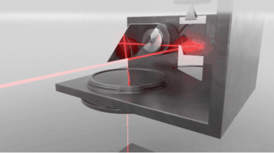
The collimating focusing head uses a mechanical device as a supporting platform, and moves back and forth through the mechanical device to achieve welding of welds with different trajectories. The welding accuracy depends on the accuracy of the actuator, so there are problems such as low accuracy, slow response speed, and large inertia. The galvanometer scanning system uses a motor to deflect the lens. The motor is driven by a certain current and has the advantages of high accuracy, small inertia, and fast response. When the light beam is irradiated on the galvanometer lens, the deflection of the galvanometer changes the angle of reflection of the laser beam. Therefore, the laser beam can scan any trajectory in the scanning field of view through the galvanometer system. The vertical head used in the robotic welding system is an application based on this principle.
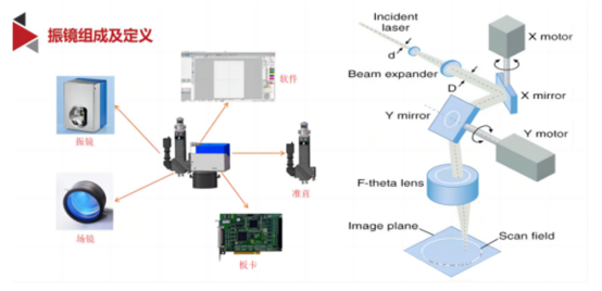
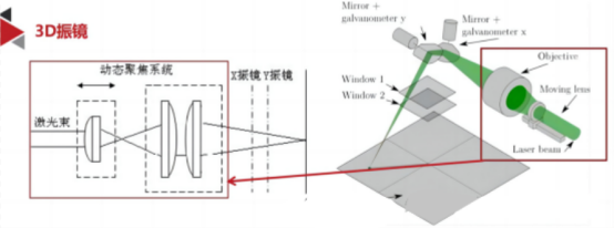
The main components of the galvanometer scanning system are the beam expansion collimator, focusing lens, XY two-axis scanning galvanometer, control board and host computer software system. The scanning galvanometer mainly refers to the two XY galvanometer scanning heads, which are driven by high-speed reciprocating servo motors. The dual-axis servo system drives the XY dual-axis scanning galvanometer to deflect along the X-axis and Y-axis respectively by sending command signals to the X and Y axis servo motors. In this way, through the combined movement of the XY two-axis mirror lens, the control system can convert the signal through the galvanometer board according to the template of the preset graphics of the host computer software and the set path mode, and quickly move on the plane of the workpiece to form a scanning trajectory.
 、
、
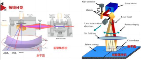
According to the positional relationship between the focusing lens and the laser galvanometer, the scanning mode of the galvanometer can be divided into front focusing scanning (left picture) and back focusing scanning (right picture). Due to the existence of optical path difference when the laser beam deflects to different positions (the beam transmission distance is different), the laser focal plane in the previous focusing scanning process is a hemispherical curved surface, as shown in the left figure. The back focusing scanning method is shown in the right figure, in which the objective lens is an flat field lens. The flat field lens has a special optical design.
By introducing optical correction, the hemispherical focal plane of the laser beam can be adjusted to a plane. Back focusing scanning is mainly suitable for applications with high processing accuracy requirements and small processing range, such as laser marking, laser microstructure welding, etc. As the scanning area increases, the aperture of the lens also increases. Due to technical and material limitations, the price of large-aperture flenses is very expensive, and this solution is not accepted. The combination of the galvanometer scanning system in front of the objective lens and a six-axis robot is a feasible solution that can reduce the dependence on the galvanometer equipment, and can have a considerable degree of system accuracy and good compatibility. This solution has been adopted by most integrators, which is often called flying welding. The welding of the module busbar, including the cleaning of the pole, has flying applications, which can flexibly and efficiently increase the processing format.
Whether it is front-focus scanning or rear-focus scanning, the focus of the laser beam cannot be controlled for dynamic focusing. For the front-focus scanning mode, when the workpiece to be processed is small, the focusing lens has a certain focal depth range, so it can perform focusing scanning with a small format. However, when the plane to be scanned is large, the points near the periphery will be out of focus and cannot be focused on the surface of the workpiece to be processed because it exceeds the upper and lower limits of the laser focal depth. Therefore, when the laser beam is required to be well focused at any position on the scanning plane and the field of view is large, the use of a fixed focal length lens cannot meet the scanning requirements.
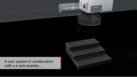
The dynamic focusing system is an optical system whose focal length can be changed as needed. Therefore, by using a dynamic focusing lens to compensate for the optical path difference, the concave lens (beam expander) moves linearly along the optical axis to control the focus position, thus achieving dynamic compensation of the optical path difference of the surface to be processed at different positions. Compared with the 2D galvanometer, the 3D galvanometer composition mainly adds a “Z-axis optical system”, which allows the 3D galvanometer to freely change the focal position during the welding process and perform spatial curved surface welding, without the need to adjust the welding focus position by changing the height of the carrier such as the machine tool or robot like the 2D galvanometer.

The dynamic focusing system can change the defocus amount, change the spot size, realize Z-axis focus adjustment, and three-dimensional processing.
Working distance is defined as the distance from the front-most mechanical edge of the lens to the focal plane or scan plane of the objective. Be careful not to confuse this with the effective focal length (EFL) of the objective. This is measured from the principal plane, a hypothetical plane in which the entire lens system is assumed to refract, to the focal plane of the optical system.
Post time: Jun-04-2024