Welding Assembly
1.Assembly Gap and Misalignment
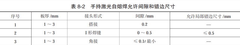
The quality of assembly is crucial to ensuring welding quality. Excessive assembly gaps or misalignment can easily cause defects such as burn-through, poor weld formation, and incomplete penetration. The assembly gap for fillet and butt joints should be as small as possible. Table 8-2 lists the requirements for gaps and misalignment in handheld laser autogenous welding.
To ensure workpiece dimensions, reduce deformation, and prevent misalignment of the area to be welded due to torsional deformation during welding, tack welding is usually required before welding. The same process method as formal welding is used for assembly tack welding. The length of tack welds is 20–30mm, and the quality requirements for tack welds (e.g., penetration depth and width) are lower than those for formal welding. A faster travel speed is generally used for tack welding than for formal welding. On the premise of ensuring reliable connection of tack welds, tack welds should be flat, long, and thin, and should not be excessively large, wide, or high. Tack welds also require adequate protection to avoid oxidation.
3.Fixtures and Clamps
Laser welding is mostly used for thin-plate welding. In thin-plate welding, welding is usually performed on the front side of the workpiece, with sufficient melting on the back side to achieve a well-formed back weld. For parameter selection: low heat input may cause incomplete fusion on the back; high heat input, while ensuring full penetration on the back, may lead to burn-through due to the gravity of molten metal or disproportionate melting width relative to workpiece thickness. To prevent burn-through, if the workpiece allows clamping, fixtures should be used to clamp the workpiece during thin-plate welding—pressing the front side and placing a copper or stainless-steel backing plate on the back side. This prevents changes in assembly gaps or misalignment caused by welding deformation and avoids thermal collapse. When the workpiece has uneven heat dissipation across regions due to structural reasons, using fixtures to balance heat dissipation is also effective, aiming to form welds with uniform dimensions on both front and back sides.
Selection of Welding Parameters
In general, laser welding parameters include laser power, laser pulse width, defocus amount, welding speed, and shielding gas.
1.Laser Power
There is a threshold laser power density in laser welding. Below this threshold, penetration depth is shallow; once reached or exceeded, penetration depth increases significantly. Plasma is generated only when the laser power density on the workpiece exceeds the threshold, indicating stable deep penetration welding. Below the threshold, only surface melting occurs (stable heat conduction welding). Near the critical condition for keyhole formation, deep penetration and heat conduction welding alternate, resulting in an unstable process with large fluctuations in penetration depth. Laser power is one of the most critical parameters in laser processing and a key determinant of weld penetration depth. For a fixed focused spot diameter, laser power density is proportional to laser power: higher power increases penetration depth and welding speed. However, excessive power causes severe overheating of the molten pool, increases weld width and heat-affected zone (HAZ), and leads to more spatter, which may contaminate the welding lens. With high power, the surface layer can be heated to boiling point and vaporized significantly within microseconds, making it ideal for material removal processes such as drilling, cutting, and engraving. With lower power, the surface takes milliseconds to reach boiling point, and the underlying layer melts before surface vaporization, facilitating good fusion welding.
2.Laser Pulse Width
Laser pulse width, or “pulse width,” is a key parameter in pulsed laser welding. It is determined by penetration depth and HAZ: longer pulse widths increase HAZ, and penetration depth increases with the square root of pulse width. However, longer pulse widths reduce peak power, so they are generally used for heat conduction welding, forming wide, shallow welds—especially suitable for lap joints of thin and thick plates. However, low peak power causes excessive heat input, and each material has an optimal pulse width for maximum penetration depth.
3.Selection of Defocus Amount
The position of the focused spot is critical in laser fusion welding. When the focus is above the workpiece surface, penetration depth is small, making deep penetration welding difficult. When the focus is below the surface, power density inside the workpiece is higher than on the surface, promoting stronger melting and vaporization, enabling energy to transfer deeper into the workpiece and increasing penetration depth. There are two defocus modes: positive defocus (focus plane above the workpiece) and negative defocus (focus plane below the workpiece). In practice, for thick plates requiring large penetration depth, negative defocus is used, with the laser focus typically 1–2mm below the workpiece surface. For thin plates, positive defocus is preferred, with the focus 1–1.5mm above the surface.
4.Welding Speed
With other parameters fixed, penetration depth decreases as welding speed increases, while efficiency improves. Excessively high speeds fail to meet penetration requirements; excessively low speeds cause over-melting, wide welds, HAZ overheating, and increased hot cracking tendency. In pulsed laser welding, speed is also determined by the maximum pulse frequency and required spot overlap—each subsequent pulse spot must overlap to some extent. Thus, for a given laser power and material thickness, there is an optimal speed range, within which maximum penetration depth is achieved at a specific speed.
5.Shielding Gas
Inert gases are often used to protect the molten pool during laser welding. While some materials may not require protection against surface oxidation, most applications do. Traditionally, Ar, N₂, and He are used for aluminum alloy laser welding to prevent oxidation. Theoretically, He is the lightest with the highest ionization energy, but at low power and high speeds, plasma is weak, minimizing differences between gases. Studies show that under the same conditions, N₂ more easily induces keyhole formation due to exothermic reactions with Al; the resulting Al-N-O ternary compounds have higher laser absorption. However, pure N₂ forms brittle Al-N phases and pores in welds. Inert gases, being lightweight, escape without causing pores, making mixed gases more effective. Recently, research on Al laser welding using Ar-O₂ and N₂-O₂ mixtures has increased.
6.Material Absorption
Material absorption of laser energy depends on properties such as absorptivity, reflectivity, thermal conductivity, melting temperature, and evaporation temperature, with absorptivity being the most critical. Factors affecting absorptivity include:
Electrical resistivity: For polished surfaces, absorptivity is proportional to the square root of resistivity, which varies with temperature.
Surface condition: Significantly affects absorptivity and thus welding results.
Operating Tips and Taboos for Handheld Fiber Laser Welding
1.Avoid Arc Radiation
Handheld fiber laser welders use class 4 fiber lasers emitting (1080±3)nm radiation with output power exceeding 1000W (depending on the model). Direct or indirect exposure can damage eyes or skin. Though invisible, the beam can cause irreversible damage to the retina or cornea. Always wear certified laser safety goggles when the laser is operating. Never look directly at the output head while the laser is powered on, even with goggles.
2.Setting Welding Parameters
Set low laser power on the touchscreen (as shown in Figure 8-2). Place the welding head’s copper nozzle against the workpiece and press the torch switch to emit laser for welding. Typical parameters: laser frequency 5000Hz, galvanometer speed 300–600, gas delay >100ms, 100% duty cycle for continuous emission. Adjust weld width based on assembly gaps; power is adjustable from 0–1000W (0–100% of maximum). After entering parameters, click “OK” and save for settings to take effect.
4.Do Not Excessively Increase Welding Speed
Welds are formed by moving the laser source (see Figure 8-3). Depth and width depend on speed and power, with typical speeds of 1–3 m/min, producing smooth, scale-free surfaces with an aspect ratio <1. For fixed current and voltage, changing speed directly affects heat input, altering penetration and width. Excessively high speeds cause insufficient heating, leading to reduced penetration, narrow width, undercut, pores, and incomplete penetration.
Mechanical cleaning: Use stainless steel brushes or pneumatic wheels to remove oxides until a bright white finish is achieved. Weld immediately after polishing; re-polish if welding is delayed >36 hours.
Chemical cleaning: Remove oxides using chemical reactions (methods vary by material). Table 8-3 lists chemical cleaning methods for aluminum alloys. Remove oil/dust with organic solvents (gasoline, isopropyl alcohol) by soaking, wiping, and drying.
5.Minimize Porosity
Hydrogen pores are common in aluminum alloy laser welding. Reduce them by removing surface moisture, oil, and oxides. Extending molten pool cooling time (by increasing pulse width) helps gases escape, as laser welding’s fast thermal cycle limits gas release. Avoid focus or negative defocus positions, where intense molten pool reactions and alloy vaporization increase porosity; use softer energy via adjusted defocus to reduce vaporization.
6.Pay Attention to Torch Holding Posture
Handheld laser torches (see Figure 8-4) are heavier than TIG torches and have thick cables, causing operator fatigue. For prolonged welding, hold the torch with both hands, keep the nozzle in contact with the workpiece, visually align the weld, and pull the torch steadily toward yourself. Adjust posture based on welding position to minimize fatigue and joint count.
7.Prevent Laser Injuries
Improper operation can cause accidents. Follow these rules:
Never stare at the laser output head during operation.
Do not use fiber lasers in dim/dark environments.
Never aim the torch at people when the device is active.
Use metal barriers within 3m of the welding area.
Restrict access to the welding zone to operators only.
Wear protective gear (certified goggles, masks, gloves). Never stare at the output head while the laser is powered on, even with goggles.
Handle the torch and cable carefully (minimum bend radius >200mm).
Disable the laser emission key when not in use.
Ensure nozzle quality for effective gas protection:
Smooth inner walls, concentric with the laser.
Replace deformed nozzles promptly to maintain steady torch movement.
Nozzle opening size (see Figure 8-6) affects weld quality: larger openings increase gas flow, accelerating solidification and raising porosity/cracking risks.
8.Avoid High Speeds for Crack-Sensitive Alloys
Handheld laser welding uses autogenous, wire-free, oscillating galvanometer torches. High speeds reduce penetration, narrow welds, cause undercut, and disrupt shielding gas coverage, worsening protection. Use lower speeds for crack-sensitive alloys.
9.Ensure Joint Quality
Temperature differences and wire-free welding may cause burn-through, craters, or crater cracks. Weld continuously to minimize stops; if stops are unavoidable (e.g., position changes, segmented welding), slow slightly (10mm) before stopping to prevent craters. Restart 20mm behind the previous crater for overlap and quality.
10.Follow Proper Torch Movement
Pull the torch toward yourself (from far to near) without lateral oscillation. Maintain steady speed while monitoring consistent weld formation. For vertical welding, use downward travel (not upward) to leverage fast solidification and ensure steady movement.
11.Avoid Undercut, Small Fillets, and Collapse in Lap Welds
For lap welds, adjust the laser incidence angle so the galvanometer covers 2/3 of the vertical plate (see Figure 8-7). This melts the vertical plate (as filler) and 1/3 of the base plate via heat conduction, forming a sufficiently sized weld after cooling. Poor lap welds weaken joint strength, reduce crack resistance, or cause structural failure—avoid undercut.
12.Reduce Reflectivity in Aluminum Alloy Welding
Aluminum reflects 60–98% of laser energy. Reflectivity drops sharply at the melting point and stabilizes when molten. Absorptivity decreases with increasing incidence angle; maximum absorption occurs at normal incidence (adjust for lens protection). Reduce reflectivity by removing oxides via mechanical/chemical cleaning.
13.Proper Shielding Gas Usage
Shielding gas affects weld formation, penetration, and width. Most gases improve quality but may have drawbacks:
Ar: Low ionization energy, high plasma formation (reducing laser efficiency) but inert, low-cost, and dense—effectively covering the molten pool (ideal for general use).
N₂: Moderate ionization energy (reduces plasma better than Ar), but reacts with aluminum/carbon steel to form brittle nitrides, reducing toughness (not recommended for these materials). Suitable for stainless steel, where nitrides enhance strength.
14.Shielding Gas Flow Rate
Gas is ejected through the nozzle at specific pressure. The nozzle’s hydrodynamic design and outlet diameter are critical: large enough to cover the weld, but restricted to prevent turbulent flow (which draws in air and causes porosity). For handheld laser welding, typical flow rate is 7L/min. Excessive flow stirs contaminants into the molten pool, compromising gas purity—select the correct flow rate.
15.Laser Focus Position
Focus position: Smallest spot, highest energy—use for spot welding or low-energy, minimal spot size requirements (see Figure 8-8).
Negative defocus: Larger spot (increases with distance from focus)—suitable for deep penetration continuous welding and deep spot welding.
Positive defocus: Larger spot (increases with distance from focus)—suitable for surface sealing or low-penetration continuous welding.
Control for full penetration welding: A slight color change on the back indicates good quality; obvious marks/penetration cause spatter or deep grooves in continuous welding. Adjust focus, energy, and waveform based on samples. Use smaller spots for thinner materials to avoid burn-through.
Post time: Aug-21-2025