Detailed Summary of Flying Laser Welding Heads
It covers component names, definitions, principles, design parameters and formula calculations, and is applicable to high-speed scanning welding (such as galvanometer systems) or remote welding applications.
1. Composition and Definition of Flying Welding Laser Welding Heads
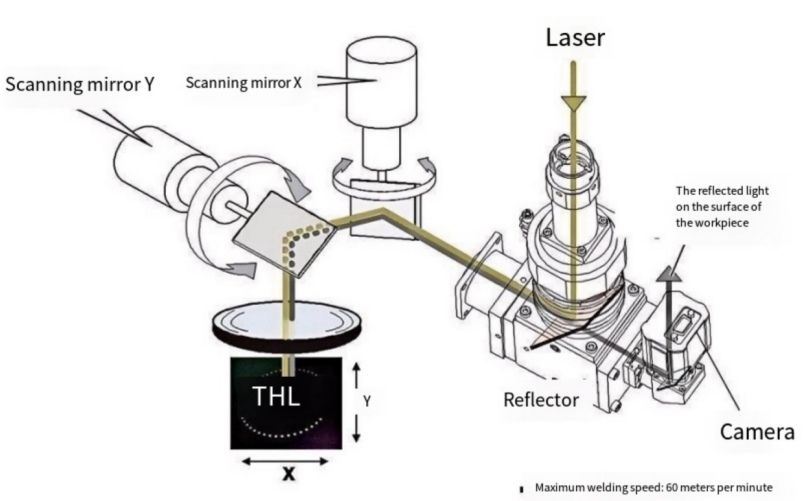
Flying welding (Scanning Laser Welding) realizes dynamic focusing through high-speed galvanometer reflecting laser beams, and is suitable for large-area and high-speed welding. Its core components are as follows:
1. Beam Collimation Module
Collimator
Function: Convert the divergent laser (NA=0.1~0.22) output by the optical fiber into a parallel beam.
Key parameters: Focal length fcoll, collimated beam diameter Dcoll.
Formula:
1.2 Galvanometer Scanning System
X/Y-axis Galvo Mirrors
Function: Change the direction of the light beam through high-speed rotating mirrors to achieve two-dimensional plane scanning.
Key parameters: Scanning speed (usually ≥10m/s), repeat positioning accuracy (<±5μrad), mirror size (needs to cover the beam diameter Dcoll).
Galvanometer motor: Servo motor or galvanometer motor with a response time of <1ms.
1.3 Dynamic Focusing Module (F-Theta Lens or Galvanometer + Flat-Field Lens)
F-Theta Lens
Function: Convert the deflection angle of the galvanometer into a linear displacement on the plane to maintain focus consistency.
Key formulas:
2. Working Principle
Beam path: Laser → Collimator → X galvanometer → Y galvanometer → F-Theta lens → Workpiece surface.
Dynamic focusing:
When the galvanometer deflection angle is θ, the focus position (x, y) is converted by the F-Theta lens as:
3. Key Design Parameters and Formulas
3.1 Spot Size Calculation
Focused spot diameter d (diffraction limit):
3.2 Scanning Range and Galvanometer Angle
Maximum scanning range L:
3.3 Welding Speed and Acceleration
Linear velocity v
3.4 Depth of Focus (DOF)
3.5 Power Density and Energy Input
Power density I:
Energy density E (pulse welding):
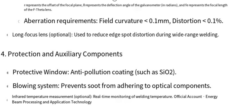
4. Aberrations and Optimization Design
4.1 F-Theta Lens Aberration Correction
Distortion: It needs to satisfy r∝θ, and the nonlinear distortion should be <0.1%.
Field curvature: Design a flat field through multi-lens groups.
4.2 Galvanometer Synchronization Error
The X/Y galvanometer delay should be <1μs to avoid elliptical spots.
5. Example of Design Process
Input requirements: Scanning range L, spot size d, welding speed v. Select F-Theta lens: Determine fθ according to L=2fθtan(θmax).
Calculate galvanometer parameters: Angular velocity ω=v/fθ, and verify the galvanometer performance.
Verify spot quality: Optimize lens group aberrations through Zemax/OpticStudio.
6. Precautions
Thermal management: Galvanometers and lenses need water cooling under high power (such as >1kW).
Anti-collision protection: Galvanometers need emergency braking to avoid mechanical collision.
Calibration: Regularly calibrate the optical path coaxiality (deviation <0.05mm).
Post time: Aug-04-2025